
A potential damage you might encounter in a DLP projector is the presentation while viewing one or more vertical lines. These lines are usually persistent (or occur after several minutes of operation) and occur even if we haven’t connected source, having white or black color.
For example, in the following projector have the permanent show two white lines.

The causes of this damage can be several, from the socket of the DMD chip until the power circuit of memories or processors management of DMD. In this article, however we will deal with a classic “light” is a classic failure of processing chip DLP. If in a DMD chip DLP projector is the heart of the processing chip then we could describe as the lung, which manages the DMD chip and how it will “work” in order to place the material we feed our projector on cloth.
The specific chip in most cases looks like this

In the bottom of the side is like this

These are so-called chip BGA technology (ball grid array). The term chip ball grid array essentially describing how this chip is connected to the electronic PCB/circuit. The BGA chip is essentially surface mount and the difference from the simple chip is that the terminals are on the bottom side to form small balls and no perimeter like we used to. In the pictures below you can see the differences of a BGA chip with a simple.


Our BGA layout gives several advantages with basic most contacts will not fit in any case in a regular layout unless we made the chip giant which of course won’t flights spatial whole circuit.
Another advantage is the lowest inductance due to the unwanted smaller contact length of BGA layout, and finally, the best temperature dissipation because of the smaller thermal resistance of many contacts/bales that allows easier flow of temperature which develops the chip to the rest of the Board and then to the environment.
Unfortunately the BGA layout in addition to advantages and disadvantages of features with the first and best that which creates the problem that we analyze in this article.
Round short chip BGA contacts are not sufficiently flexible as the classics away “legs” of the simple chip so when expansion/contraction of the circuit (PCB) because of the heat, some solder between chip and circuit can break, detach, creating problems in the functioning of the whole circuit.


The most classical fault that maybe many of you may have already encountered, happens in BGA chip on the Laptop video cards resulting in the appearance of lines or various artifacts on the screen.
Such a breakdown in contacts a BGA chip since first diagnosed, is solved by the so-called reflow, epanakollisi i.e. chip contacts.
Such a process in BGA chip is made with specialized instruments such as hot air station or the IR station since there is no direct access to the contacts you want to epanakollisoyme.
It is important to know the temperature and soldering time each particular chip (refers to any manufacturer’s datasheet) in order not to go beyond the limit and “bake” the chip and circuit yet.
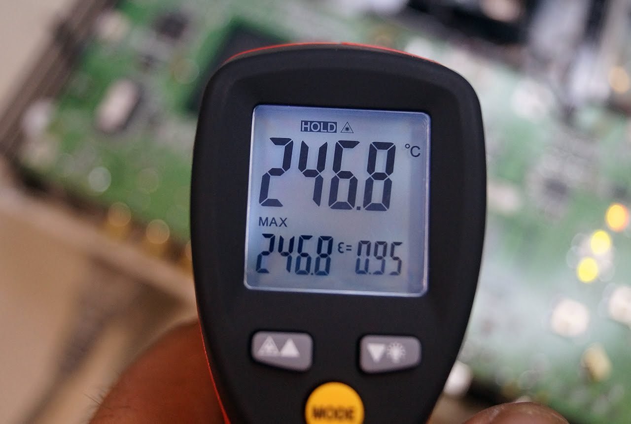
Roughly and on average, we would say that you need to heat the chip around 250 degrees for time between 30 seconds and a minute. I did that particular chip reflow with hot air station, with a small head, in order to better control airflow in order not to cause some unintended elevation of smaller material near the chip.
Making firm circular motions trying to give the desired temperature in the chip in all its surface (important) as evenly as we can. When you reach the desired temperature trying to maintain for the time you need in order to achieve the epanakollisi.

If near the BGA chip there are smaller materials it is advisable to cover them with foil so the temperature to anaklate and not going through them, as we see in the photo below/example.

Important throughout the process to ensure a successful reflow is to check the temperature with a laser instrument in order to know where we are going with relative accuracy.

A wrong or bad solder will unfortunately mean that detachment chip contacts will resume in a short time and will have to repeat the procedure from the beginning although initially seeming success. Unfortunately by doing reflow hot air station with the sole us ally in order to judge whether the weld is successful or partially successful experience in respective solder because there is no visual contact, without this meaning that not everyone with the appropriate equipment and patience to achieve excellent result.
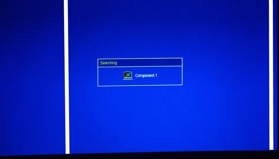
In our case the epanakollisi became successful and behold the end result, the projector image “got rid of” at last the white vertical lines that the render inoperable.

I hope you will find our technical article interesting and why not even useful.
Good views
Nikos Tswlas
4 Comments
Mine is a RD805 mini projector,it got verticle lines to the right side ..the screen now is in two halves,on your left is clear but to the right has those lines,help.
My View sonic PJD 5126 Projector showing Vertical Lines more. How to solve this problem
if you use some flux on the outside edges of the chip prior to heat, the capillary action of the heat will draw flux under chip and aid in the resoldering of the balls. I’d also use some thermal paste and a small heatsink on top of the DLP chip if possible to decrease operating temp.
what if it’s a BARCO udm and i have vertical green lines two running down about two feet apart from each other?